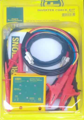
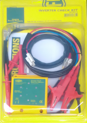
Inverter Check Kit by REFCO
Price: 492.00лв.
- Code:514
- Weight:0.000 Kgs
Inverter Check Kit Operating Instructions
INVERTER PHASE CHECK MODULE
Performing the Tests – Checking the Inverter Phase Outputs
Checks Inverter Output – shows non-functioning-output devices or damaged output stage. Checks serial-link communication between indoor and outdoor units. Identifies connection problems or non- working Pc-boards. Invaluable aid for analysis of inverter problems.
ATTENTION!
Before commencing any tests, SWITCH-OFF ALL POWER SOURCES and WAIT for a MINIMUM OF 3 MINUTES to allow all capacitor voltages to decay. Before disconnecting of connecting any terminals, chek that all voltages are zero.
This Test Equipment
• MUST NOT BE USED in damp or wet conditions
• Must only be used by a competent Engineer
• Is not intended for permanent connection
• Has a max voltage of 440v and a max power of 1.8 watts
Guarantee
Your new INVERTER-CHECK-KIT has been developed in accordance with the latest occupational health and ergonomic requirements and reflects the latest state-of-the-art technology. REFCO Manufacturing Ltd has been certified in accordance with DIN EN ISO 9001: 2008. Regular quality control checks as well as an accurate manufacturing process guarantee reliable functionality and are the basis for the REFCO guarantee, in accordance with the General Terms and Conditions of Sale and Delivery applicable on the day of delivery. Damages arising from obvious abuse or wear are excluded from the guarantee.
Environment
The INVERTER-CHECK-KIT has been developed for long term use. REFCO takes energy saving and environmental impact into consideration when procuring materials and manufacturing its products. REFCO Manufacturing Ltd feels responsible for all of its products throughout their entire lifespan and has therefore been certified in accordance with DIN EN ISO 14001: 2004. When decommissioning the device, users should observe the disposal regulations applicable in their country.
The test is carried out using the 3 connection terminals labelled 1, 2, and 3 on the Inverter Checker:
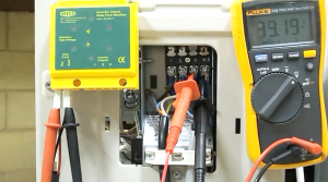
1. With all power switched off, disconnect the three wires from the compressor, making sure to note down which wire goes to what terminal, now connect the 3 probes from the Inverter Checker outputs labelled 1, 2, and 3 to the end of compressor wires (as shown below).
2. With the three wire connections safely made from the outdoor inverter printed circuit board to the Inverter Checker, place the module on a dry surface, preferably in the shade, where the lights can be seen through the windows in the facia panel. Now switch the power back on and operate the system. Please note that most units will have a time delay/cycle protector, so you may have to wait 3 to 5 minutes for the system to start operating, this will depend on make and model of your system.
3. If the inverter outputs are “Good” then all six lights will illuminate, showing red, yellow, and blue. If there is a problem with the output (power) board, or with the printed circuit board then one or more of the lights will not be lit.
NOTE: The inverter boards from some manufacturers incorporate a safety cut-out which stops the inverter after a few seconds if the compressor is not connected. In these cases the lights on the Inverter Checker will only light for a few seconds, but provided all six lights turn on then the inverter printed circuit board is probably ok. A second test, with both the compressor and the Inverter Checker connected, should then provide further confirmation.
Performing the Tests – Checking the Data Flow
This is a simple data connections check and does not need to be an inverter driven system.
When the system is operating, data flows between the outdoor unit printed circuit board and the indoor unit printed circuit board.
1. To check the data flow, connect the red and black data probes to the terminal feeding the indoor unit.
2. With the system on and operating you should see at least one of the data lights flashing. The make and model of your system will determine if both data lights flash or only one. This flashing is not symmetrical and varies in intensity and frequency depending on the type and amount of data being transmitted.
3. If you have no data lights flashing, then check that the connecting cable is not damaged and that the connections at both ends are made properly. Also check that the outdoor unit and indoor unit are grounded/earthed to each other.


